TM 55-1510-220-10
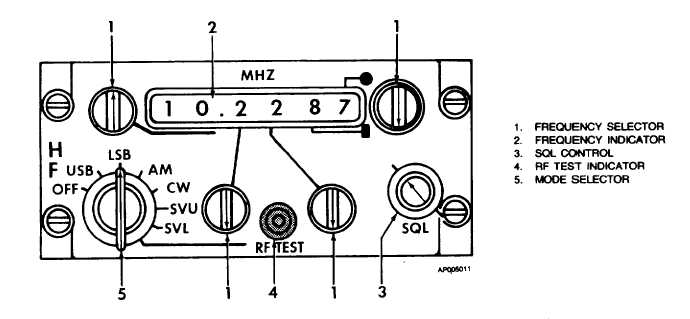
Figure 3-7. HF Control Panel (718 U-5)
(c)
No. 4 radio monitor control (audio
control panel, fig. 3-1) Set to mid
position.
(d)
Volume control (audio control
panel) Adjust.
(e)
Squelch control (HF control panel) As
required.
(f)
Frequency control (HF control
panel) Set desired frequency.
(4)
Transmitter operating procedure.
(a)
Transmitter-interphone
selector
switch (audio control panel) No. 4
position.
(b)
Function selector (HF panel) Set to
USB, LSB, or AM.
(c)
MIC HEADSET-OXYGEN MASK
switch (instrument panel) As desired.
(d)
SQL knob (HF panel) Adjust to just
quiet noise when no signal is being
received.
(e)
MIC switch Depress to transmit.
3-14. HF COMMAND SET (718 U-5).
a.
Description. The HF command set provides long-
range voice communications within the frequency range of
2.000 to 29.999 MHz and employs either standard amplitude
modulation (AM), lower side-board (LSB), or upper side-
board (USB) modulation. The distance range of the set is
approximately 2,500 miles and varies with atmospheric
conditions. The unit is protected by a 3-ampere HF RCVR
and the 25-ampere HF PWR circuit breaker on the overhead
circuit breaker panel (fig. 2-27). The control panel is located
on the pedestal extension.
b.
Controls/Indicators and Functions.
(1)
HF Control Panel (pedestal extension, (fig.
3-7).
(2)
Frequency selector. Selects the desired
operating frequency.
(3)
Frequency indicator. Displays the selected
frequency.
(4)
SQL control. Adjusts squelch level.
Change 2
3-15


