TM 55-1510-219-10
NOTE
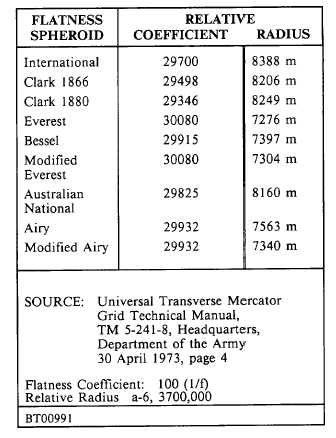
Values for various spheroids are
listed in Table 3-1.
4. If values are correct, return CDU to
normal
display
mode
by
momentarily setting data selector to
any position except UTM WYPT. If
values are to be changed, continue
with following steps:
NOTE
The INS geographic position, as
read in L/L displays, will not be
affected by any changes in these
coefficients.
5. Keys "2"or "8" Press to indicate
following is the flatness coefficient.
(Observe
INSERT/ADVANCE
pushbutton
light
illuminates.)
6. Load earth flatness coefficient by
pressing
keyboard
keys
in
sequence.
(Example: 2 9 4 9 8 = 29498. Observe number
appears in left display as keys are pressed.)
7. INSERT/ADVANCE
pushbutton
Press.
(Observe INSERT/ADVANCE pushbutton light goes
out.)
8. Keys "4" or "6" Press, to indicate
following load is relative earth
radius.
(Observe
INSERT/ADVANCE
pushbutton
light
illuminates.)
9. Load
relative
earth
radius
by
pressing
keyboard
keys
in
sequence.
(Example: 8 2 0 6 m = 8206. Observe numbers
appear in the right display as keys are pressed.)
NOTE
Zone symbol is to be ignored.
Table 3-1. Various Values for UTM Grid Coefficients
10. INSERT/ADVANCE
pushbutton
Press.
(Observe
INSERT/ADVANCE
pushbutton
light
extinguishes.)
11. Data selector UTM POS.
(Observe coordinate will reflect values of new
spheroid.)
(6)
Insert present position.
(7)
Perform abbreviated INS interface test As
required:
NOTE
Assuming a level aircraft, attitude
indicators
will
become
level
during alignment State "8" and
remain level in all modes until INS
is shut down. Warning indicators
for INS attitude signals from INS
are valid while attitude sphere
display is level.
3-49


