TM 55-1510-219-10
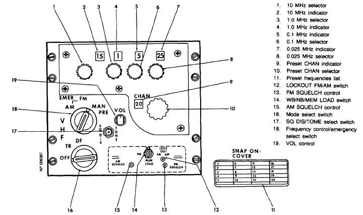
Figure 3-5. VHF AM/FM Control Panel (AN/ARC- 186)
b. Controls and Indicators.
(1) VHF AM/FM control panel (fig. 3-5).
CONTROL
FUNCTION
10 MHz selector
Selects receiver-transmitter fre-
quency in increments of 10 MHz
from 30 to 150 MHz. Clockwise
rotation increases frequency.
10 MHz
Indicates manually selected re-
indicator
ceiver-transmitter frequency in
10 MHz increments from 30 to
150 MHz.
1.0 MHz selector
Selects receiver-transmitter fre-
quency in 1.0 MHz increments.
Clockwise rotation increases fre-
quency.
1.0 MHz
Indicates manually selected re-
indicator
ceiver-transmitter frequency in
1.0 MHz increments.
0.1 MHz
Indicates manually selected re-
indicator
ceiver-transmitter frequency in
0.1 MHz. increments.
0.1 MHz selector
Selects receiver-transmitter fre-
quency in 0.1 Mhz increments.
Clockwise rotation increases fre-
quency.
0.025 MHz
Indicates manually selected re-
indicator
ceiver-transmitter frequency in
0.025 MHz increments.
0.025 MHz
Selects receiver-transmitter fre-
selector
quency in 0.025 MHz incre-
ments. Clockwise rotation in-
creases frequency.
CHAN indicator Selects preset channel from 1 to
20. Clockwise rotation increases
number selected.
LOCKOUT FM/
Screwdriver adjustable three-
AM switch
position switch. Warning tone
announces lockout.
Center
Selects AM or FM band.
AM
Disables AM band.
FM
Disables FM band.
FM SQUELCH
Screwdriver adjustable potenti-
control
ometer. Squelch fully overdriven
at full counter-clockwise posi-
tion. Clockwise rotation in-
creases input signal required to
open squelch.
WB/NB MEM
Three-position switch.
LOAD switch
3-10


