TM 55-1510-219-10
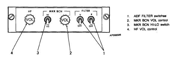
Figure 3-2. Radio Control Panel
NOTE
The PRESET channel selector and
manual frequency selectors are
inoperative
when
the
mode
selector is set to GUARD position.
The receiver-transmitter will be
set to the emergency frequency
only.
The transmit and receive sections of the UHF unit
operate independently but share the same power supply
and frequency control circuits.
Complete provisions only are installed for voice
security device KY-28 or KY-58 to locate on the
pedestal extension near the radio set. The UHF
command set is protected by the 7 1/2 ampere UHF
circuit breaker on the overhead circuit breaker panel
(fig. 2-26). Figure 3-3 illustrates the UHF command
set. The associated blade type antenna is shown in
figure 2-1.
b. Controls and Indicators.
(1) UHF control panel fig. 3-3.
CONTROL
FUNCTION
Manual
Selects hundreds digit of fre-
frequency
quency (either 2 or 3) in MHz.
selector
(hundreds)
Manual
Selects tens digit of frequency (O
frequency
through 9) in MHz.
selector (tens)
Manual
Selects units digit of frequency
frequency
(O through 9) in MHz.
selector (units)
Manual
Selects tenths digit of frequency
frequency
(O through 9) in MHz.
selector (tenths)
Manual
Selects hundredths and thou-
frequency
sandths digits of frequency (00,
selector
25, 50, or 75) in MHz.
(hundredths and
thousandths)
Preset channel
Selects one of 20 preset channel
selector
frequencies.
Mode selector
Selects operating mode and
method of frequency selection.
MANUAL
Enables the manual selection of
any one of 7,000 frequencies,
PRESET
Enables selection of any one of
20 preset channels. preset chan-
nel selector switch.
GUARD
Selection automatically tunes the
main receiver and transmitter to
3-5


