TM 1-1510-225-10
3C-3
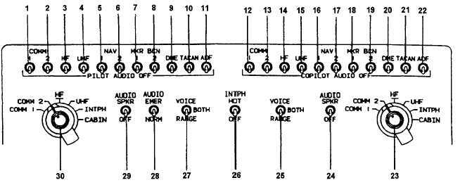
1. Pilot's COMM 1 Switch
2. Pilot's COMM 2 Switch
3. Pilot's HF Switch
4. Pilot's UHF Switch
5. Pilot's NAV 1 Switch
6. Pilot's NAV 2 Switch
7. Pilot's MKR BCN 1 Switch
8. Pilot's MKR BCN 2 Switch
9. Pilot's DME Switch
10. Pilot's TACAN Switch
11. Pilot's ADF Switch
12. Copilot's COMM 1 Switch
13. Copilot's COMM 2 Switch
14. Copilot's HF Switch
15. Copilot's UHF Switch
16. Copilot's NAV 1 Switch
17. Copilot's NAV 2 Switch
18. Copilot's MKR BCN 1
Switch
19. Copilot's MKR BCN 2
Switch
20. Copilot's DME Switch
21. Copilot's TACAN Switch
22. Copilot's ADF Switch
23. Copilot's XMTR Selector
24. Copilot's AUDIO/SPKR
Switch
25. Copilot's VOICE/RANGE
Switch
26. INTPH HOT/OFF Switch
27. Pilot's VOICE/RANGE
Switch
28. AUDIO EMER/NORM
Switch
29. Pilot's AUDIO SPKR
Switch
30. Pilot's XMTR Selector
Figure 3C-1. Dual Audio Control Panel
(30) Pilot’s XMTR Selector – Selects COMM
1, COMM 2, UHF, HF, INTPH, or CABIN.
c. Normal Operation.
(1) Turn On.
1. Aircraft dc power – ON.
NOTE
It is presumed the AVIONICS MASTER
POWER Switch is ON and that normally
used avionics circuit breakers remain
pressed.
The circuit breakers of routinely used
avionics systems are normally left pressed.
2. AVIONICS MASTER POWER Switch
– ON.
(2) Receive.
1. AUDIO SPKR Switches (audio panel)
– SPKR.
2. AUDIO EMERG / NORM Switch –
NORM.
3. Move each audio panel select switch
ON then OFF, separately, to verify
audio output from speakers for each
system and adjust volume.
NOTE
Audio panel switches and volume controls
are routinely left in positions of normal
use.
All audio volume controls are on the radio
section of the instrument panel, except for
controls to the HF, UHF, and TACAN
systems located on the pedestal.


