TM 1-1510-224-10
WARNING
The
system
performs
only
the
functions of weather detection or
ground mapping. It should not be
used nor relied upon for proximity
warning or anti-collision protection.
Output power is radiated during test
mode.
CAUTION
If the radar system is to be operated
in any mode other than standby while
the aircraft is on the ground: Direct
the nose of the aircraft so that the
antenna scan sector is free of large
metallic objects such as hangars or
other aircraft for a distance of 100
feet (30 meters).
Do not operate during refueling of
aircraft or defueling operation within
100 feet (30 meters).
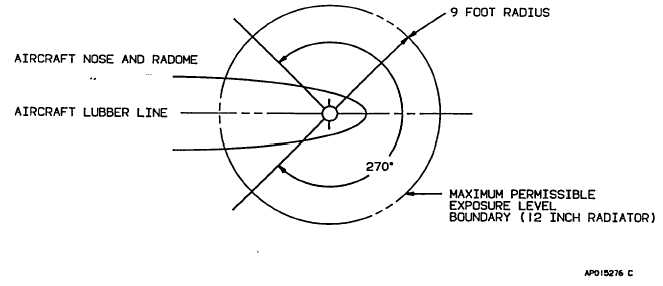
Do not operate if personnel are
standing too close to the 270-degree
forward sector of the aircraft (fig. 3-
31).
Operating
personnel
should
be
familiar with FAA AC 20-68B.
In the weather detection mode, precipitation intensity
levels are displayed in four colors, contrasted against a
deep black background. Areas of very heavy rainfall will
appear in magenta, heavy rainfall in red, less severe in
yellow, light rain in green, and little or no rainfall in black
(background). The correlation of precipitation intensity
and the color of displayed weather is shown in table 3-12.
Range marks with identifying numerics, displayed in
white, are provided to facilitate evaluation of storm cells.
Selection of the ground mapping (GMAP) function will
cause system parameters to be optimized to improve
resolution and enhance identification of small targets at
short range. The reflected signal from ground surfaces
will be displayed as magenta, yellow, or cyan (most to
least reflective).
a.
Radar Control Panel Controls, Indicators,
and Functions:
(1)
Range switches. Two momentary-
contact pushbutton switches (placarded with an up arrow
on the left switch, and a down arrow on the right), are
used to select the operating range of the radar (and the
lightning
Figure 3-31. Maximum Permissible Exposure Level
3-81


