TM 1-1510-224-10
Time mark pulse (time synchronization)
Navigation data block (position, velocity, and time)
Error state vector data block (9 element ESV, time)
TM/covariance data block (time, TM time, covariance)
Status data block (status including DOP's and FOMN)
Section IV. RADAR AND TRANSPONDER
3-30. RADAR AND TRANSPONDER EQUIPMENT
GROUP DESCRIPTION.
The radar and transponder group consists of a
weather radar, lightning sensor system, transponder, and
encoding altimeter indicator. The transponder and radar
group includes an identification, position, emergency
tracking system, and a radar and lightning sensor system
to locate potentially dangerous weather areas.
3-31. WEATHER RADAR SYSTEM (WC-650).
The weather radar system is a light weight, X-band
digital' radar with alphanumerics designed for weather
detection and analysis and ground mapping. The radar
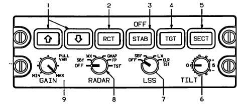
system is controlled from the radar control panel (fig. 3-
29), located on the pedestal extension (fig. 2-14). Radar
information is displayed on the pilot's and copilot's EHSI.
NOTE
The weather radar may display false
echoes and spikes on all ranges
when
the
VHF-FM
(SINCGARS)
transceiver is transmitting.
The primary purpose of the system is to detect storms
along the flight path and give the pilot a color visual
indication of their rainfall intensity. After proper
evaluation, the pilot can chart a course to avoid these
storm areas.
Figure 3-30 depicts a typical EFIS weather test
pattern (120 degree scan).
1. Range Switches
2. Rain Echo Attenuation Compensation Technique Pushbutton Selector Switch
3. Attitude Stabilization Pushbutton Selector Switch
4. Target Alert Pushbutton Selector Switch
5. Sector Scan Angle Pushbutton Selector Switch
6. Antenna Tilt Angle Control
7. Lightning Sensor System Mode Selector Switch
8. Radar System Mode Selector Switch
9. Radar Receiver Gain Control
A93FE00D0111 C
Figure 3-29. Weather Radar/Lightning Sensor System Control Panel
3-79


