TM 1-1510-223-10
2-78 Change 3
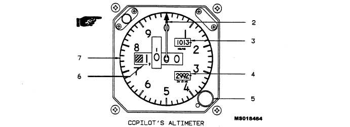
1. Deleted
2. Altitude Indicator Needle
3. Barometric Pressure Counter-Drum Indicator Window (Millibars)
4. Barometric Pressure Counter-Drum Indicator Window (Inches of Mercury)
5. Barometric Pressure Setting Knob
6. Counter-Drum Altitude Display
7. Altitude Scale
Figure 2-34. Copilot’s Barometric Altimeter
They indicate the rate at which the aircraft ascends or de-
scends based on changes in atmospheric pressure. The
indicator is a direct reading pressure instrument requir-
ing no electrical power for operation.
2-85. ACCELEROMETER.
An accelerometer, located on the instrument panel,
registers and records positive and negative G loads im-
posed on the aircraft. One hand moves in the direction of
the G load being applied while the other two (one for posi-
tive G loads and one for negative g loads), follow the indi-
cating pointer to its maximum travel. The recording
pointers remain at the respective maximum travel posi-
tions of the G’s being applied, providing a record of maxi-
mum
G
loads
encountered.
Depressing
the
push-to-reset knob at the lower left corner of the instru-
ment allows the recording pointers to return to the normal
position.
2-86. FREE AIR TEMPERATURE (FAT) GAGE.
The free air temperature gage, mounted outboard of
the pilot’s seat (fig. 2-8), indicates the outside air temper-
ature in degrees celsius.
2-87. STANDBY MAGNETIC COMPASS.
WARNING
Inaccurate indications on the standby magnetic
compass will occur while windshield heat, ra-
dome anti-ice, air conditioning, or EFIS are be-
ing used or the sunvisors are in the front position.
The standby magnetic compass (fig. 2-8), located be-
low the overhead control panel, is used in the event of
failure of the compass system, and for instrument cross
check. Readings should be taken only during level flight
since errors may be introduced by turning or accelera-
tion. A compass correction chart, indicating deviation
factors, is located on the magnetic compass.
2-88. MISCELLANEOUS INSTRUMENTS.
a. Warning Annunciator Panel. The warning annun-
ciator panel, located near the center of the instrument
panel below the glareshield (fig. 2-37 and 2-36), contains
red fault annunciators. Illumination of a red fault annun-
ciator signifies the existence of a hazardous condition
requiring pilot attention. Table 2-6 lists the red fault an-
nunciators, and the causes for their illumination.