TM 1-1510-223-10
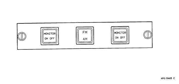
Figure 3-2. VHF-FM IF/AM Alternate Communication Switch Panel
switch is depressed to the second level or the respective
cockpit floor microphone switch is depressed, and routes
the selected transceiver's received audio to the headset,
regardless of the whether transceiver audio monitor
control is on or off.
(a)
PVT. This position is not used in this
installation.
(b)
ICS.
Selects
intercom
system.
Intercom
will
be
activated
when
control
wheel
microphone switch is depressed to the first or second
level, or when cockpit floor microphone switch is
depressed.
(c)
Position 1. Selects VHF-AM #1
transceiver.
(d)
Position 2. Selects VHF-FM (SINC-
GARS)
transceiver
or
VHF-AM
#2
transceiver
depending upon the position of the AM/FM alternate
communication selector switch (pedestal extension, fig.
2-12).
(e)
Position
3.
Selects
#1
UHF
transceiver.
(f)
Position 4. Selects HF transceiver or
VOW transceiver.
(g)
Position
5.
Selects
#2
UHF
transceiver (BU VOW).
(6)
Intercom mode selector switch. The three-
position intercom mode selector switch, placarded HOT
MIC, NORM, ICS OFF, controls the operating mode of
the intercom system.
(a)
HOT MIC. Microphone will be
continuously connected to intercom system except when
transmitter-intercom
selector
switch
is
set
to
a
transceiver, and control wheel microphone switch is
depressed to the second level, or cockpit floor
microphone switch is depressed.
(b)
NORM.
Microphone
will
be
connected to intercom system only when the control
wheel microphone switch is depressed to the first level.
If the transmitter- selector switch is set to the ICS
position, the intercom will also be activated when the
control wheel microphone switch is depressed to the
second level.
(c)
ICS OFF. Deactivates intercom
system.
d.
Normal Operation.
(1)
Turn-on procedure:
1.
BATTERY switch (overhead control panel, fig.
2-13) - ON.
3-4