TM 1-1510-218-10
2-14
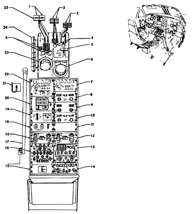
Figure 2-7. Control Pedestal C D1
1. Power Levers (2)
2. Propeller Levers (2)
3. Condition Levers (2)
4. FRICTION LOCK Knobs
5. WING FLAP Switch
6. RUDDER TAB Control and Position Indicator
7. ICS #2 Control Panel
8. COMM 1 Control Panel
9. COMM 2 Control Panel
10. NAV 1/NAV 2 Control Panel
11. Blank Panel
12. ADF Control Panel
13. UHF Control Panel
14. HF Control Panel
15. IFF Antenna Select Panel
16. Transponder Control Panel
17. Alternate Landing Gear Extension Handle
18. YAW DAMP/RUDDER BOOST Control Panel
19. AP/DME Control Panel
20. AUTOPILOT Mode Selector Panel
21. Landing Gear Alternate Engage Handle
22. ICS #1 Control Panel
23. Aileron Tab Control and Position Indicator
24. ELEVATOR
Tab
Control
and
Position
Indicator
25. Autopilot Go-Around Button
PROVISIONS ONLY ARE
INSTALLED.
EITHER
OF
TWO
SETS
M AY
BE
INSTALLED.
INSTALLED
ONLY
IF
APX-101
TRANSPONDER IS INSTALLED
*
* *
*
* *