TM 1-1510-218-10
3A-8
NOTE
To adjust volume when audio is not being
received, turn squelch switch OFF, adjust
volume for comfortable noise level, then
turn squelch switch ON.
3. Volume – Adjust.
4. SQUELCH – As desired.
(5) Transmitter Operating Procedure.
1. Transmitter selector – No. 3 position.
2. UHF control panel – Set required
frequency using either PRESET or
MANUAL frequency select controls.
3. Microphone jack selector switch – As
desired.
4. Microphone
switch
–
Press
to
transmit.
(6) Shutdown Procedure. Function selector
switch – OFF.
3A-9. VHF COMMAND SET (VHF-20B).
a. Description. The VHF command set is a
line-of-sight
radio
transceiver
which
provides
transmission and reception of amplitude modulated
signals in the very high frequency range of 116.000 to
151.975 MHz for a distance range of approximately 50
miles. Two VHF radio sets are installed placarded
COMM 1 and COMM 2. Audio signals are applied
through the pilot and copilot transmitter selector
switches and through the pilot and copilot VHF-1 audio
switches to their respective headsets. The VHF radio
sets are protected by a 10-ampere VHF # 1 and VHF
# 2 circuit breakers located on the overhead circuit
breaker panel, Figure 2-16, Sheets 1 and 2. Figure
3A-4 illustrates the VHF command set control panel.
The associated antenna is shown in Figure 2-1.
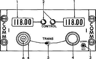
b. Controls and Functions.
(1) Frequency Indicator. Indicates operating
frequency of set.
(2) CONTROL Indicator. Indicates which
control head is in operation.
(3) COMM
TEST
Switch.
Overrides
automatic squelch circuit.
(4) Frequency Selectors. Selects desired
operating frequency of set.
(5) TRANS Switch. Selects which of two
control heads determines operating frequency of set.
(6) VOL OFF Control. Adjusts volume of
received audio and turns set on or off.
c. Normal Operation.
(1) Turn On Procedure.
1. VOL control – Turn clockwise.
(2) Receiver Operating Procedure.
1. Frequency selector – Select desire
frequency.
2. VOL control – As required.
(3) Transmitter Operating Procedure.
1. Transmitter selector switch – VHF 1 or
VHF 2.
2. Microphone Switch – Press.
(4) Shutdown Procedure.
1. VOL
control
–
Counterclockwise,
OFF.
1. Frequency Indicator
2. CONTROL Indicators
3. COMM TEST Switch
4. Frequency Selector
5. TRANS Switch
6. VOL OFF Control
Figure 3A-4. VHF Control Panel