
TM 55-4920-227-15
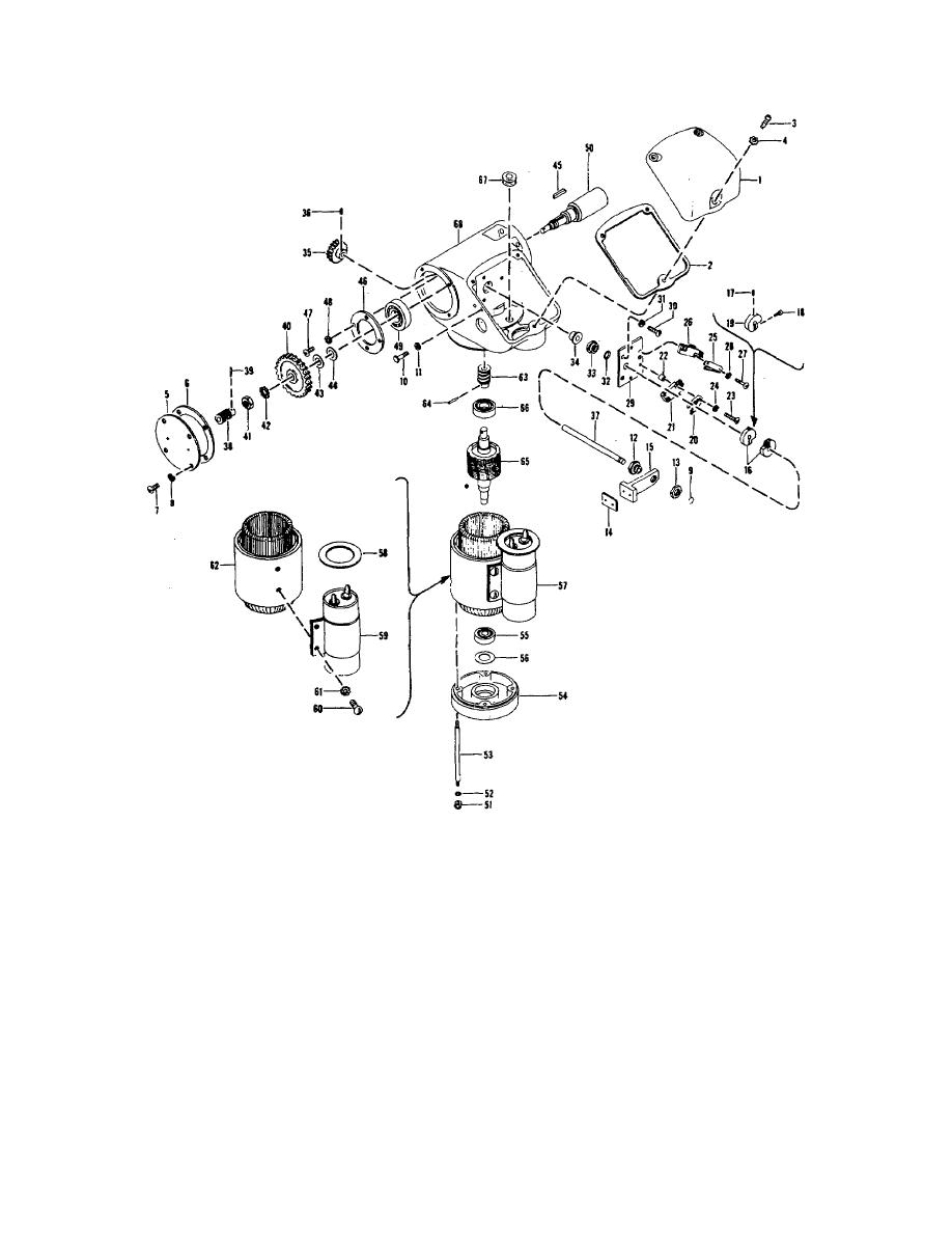
Figure 17. Electric remote control, exploded view.
and remove the wound stator assembly (57)
(38). Remove the gear (40) and shims (43
from the gearcase.
and 44) from the shaft (50).
(8) Maneuver the rotor assembly (65) and
(10) Remove the four screws (4 7) and washers
remove the rotor assembly from the worm
(48) and remove the bearing clamp (46), ball
gear (40). Remove the taper pin (64) and
bearing (49), and shaft (50) from the
press the worm (63) from the rotor. Remove
gearcase (68). Remove the taper pin (39)
the ball bearings (66 and 55) and shim (56)
and press the worm (38) from the shaft (50).
from the rotor assembly.
(11) Remove the two screws (60) and
(9) Remove the nut (41), lockwasher (42), key
lockwashers (61) and remove the
(45), and pull the worm gear (40), over worm
AGO 6729A
30

