TM 55-4920-429-13
SECTION II OPERATION
2-2. DESCRIPTION AND FUNCTION OF OPERATORS CONTROLS
AND INDICATORS.
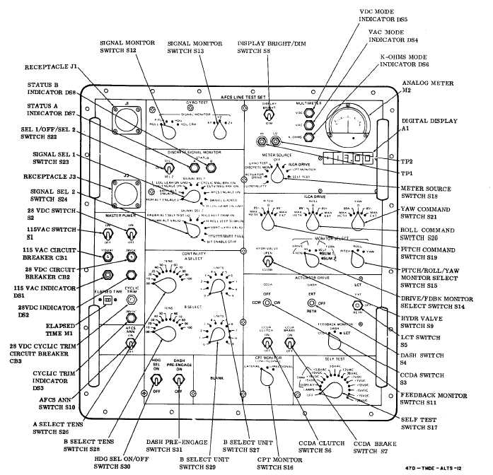
The panel and the circuits of the test set are divided into 11 distinct sections, as indicated by the group-
ing of switches and indicators on the test set front panel. (See fig. 2-2. ) The panel also includes two
binding posts, HI (TP1), LO (TP2), and two cable receptacles, J1 and J3. The switches and indicators
in each of these sections are listed and described in table 2-1.
Figure 2-2. AFCS Line Test Set Controls and Indicators
2-3

