
TM 55-4920-221-14
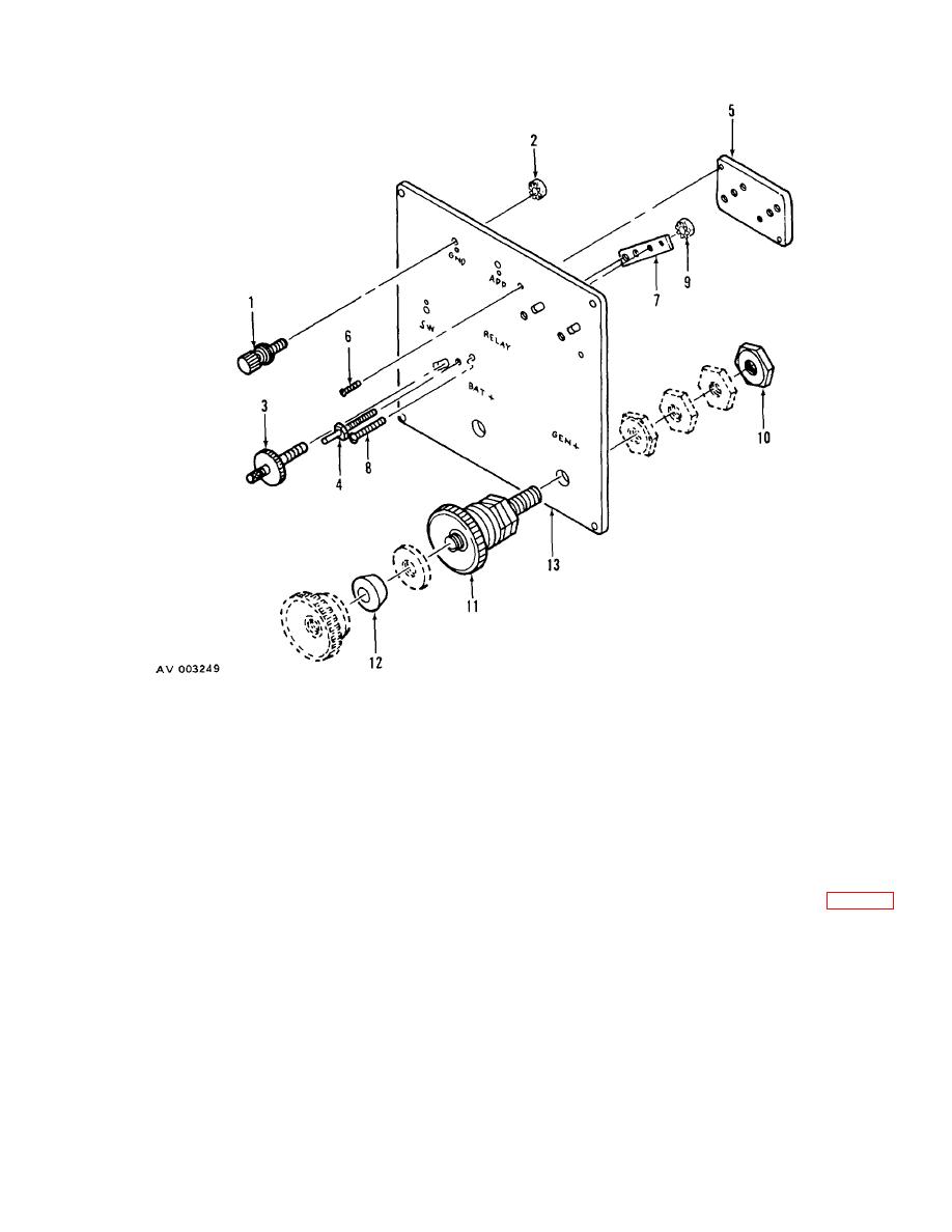
1.
Binding post
6.
Screw
11. Binding post
2.
Nut
7.
Lower back plate
12. Lug clearance washer
3.
Relay clamping post
8.
Screw
13. Relay mounting pad
4.
Relay mounting stud
9.
Nut
5.
Upper back plate
10.
Jamnut
Figure 9. Relay Pad, Exploded View.
on relay mounting pad (13).
(3) Install BAT + binding post in a similar
manner.
e. Installation.
(4) Attach lower back plate (7) on rear of
(1) Attach relay pad assembly (27, figure 7)
relay mounting pad (13) with screw (8) and nut (9).
on front of control panel with four screws (28) and nuts
(29).
(5) Align holes in plate and pad. Install relay
mounting stud (4) and relay clamping post (3).
(2) Install bus bar (26) on BATT+ and GEN+
terminals of relay pad assembly with terminal thumb
(6) Attach upper back plate (5) on rear of
knobs.
relay mounting pad (13) with two screws (6).
(3) Install and secure bus bar (31) on BATT+
(7) Align holes in plate and pad, and install
terminal on rear of relay mounting pad assembly, with
two relay mounting studs (4) and two relay clamping
two special nuts, jamnut, and screw (25).
posts (3).
(8) Attach three binding posts (1) with nut (2)
34
