TM 55-1510-222-10
located in the unpressurized portion of the aircraft
behind the aft bulkhead, lower the pressure in the
system to 400 PSI, and route oxygen to the regulator
control panels. Both cylinders are interconnected, so
refilling can be accomplished through a single filler
valve located in the aft right side of the fuselage
exterior. A pressure gage is mounted in conjunction
with the filler valve, and each cylinder has a pressure
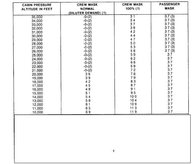
gage. Table 2-4 shows oxygen flow planning rates vs.
altitude. Table 2-5 shows oxygen duration capacities of
the system.
Table 2-4. Oxygen Flow Planning Rates vs Altitude
(All Flows In LPM Per Mask At NTPD)
NOTES:
(1) Based on minute volume of 20 LPM-BTPS (Body Temperature and Pressure Saturated).
(2) Use 100% oxygen above 20,000 feet
(3) Not recommended for other than emergency descent use above 25,000 feet.
If average climb or descent flows are desired, add the values between altitudes and divide by the number
values used.
For example, to determine the average rate for a uniform descent between 25,000 feet and 15,000 feet
perform the following:
5.9 + 6.2 + 6.6 + 6.9 + 7.2 + 7.6 + 3.9 + 4.2 + 4.5 + 4.8 + 5.1 11 = 5.7 LPM
This method is preferred over averaging the extremes as some flow characteristics vary in such a way as to
yield an incorrect answer.
2-52