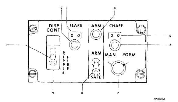
TM 55-1510-222-10
1.
RIPPLE FIRE Switch
6.
Chaff Counter Setting Knob
2.
Flare Counter Setting Knob
7.
MAN/PGRM Selector Switch
3
Flare Counter Indicator
8.
ARM-SAFE Switch
4.
ARM Light
9.
RIPPLE FIRE Switch Cover
5.
CHAFF Counter Indicator
Figure 4-3. Flare Dispenser Control Panel
2.
Chaff. Upon receiving an alert from
the aircraft radar warning system, the pilot or copilot will
fire the chaff and initiate an evasive maneuver. The
number of burst/salvo and number of salvo/program and
their intervals is established by training doctrine and will
be set into the programmer prior to takeoff (refer to TM
9-1095-206-13
&
P
for
procedures
on
setting
programmer). If desired, the operator may override the
programmed
operational
mode
and
fire
chaff
countermeasures manually by moving the dispenser
function selector switch to MANUAL and pressing the
dispenser switch.
(b) Firing responsibility. When the pilot or
copilot observes a missile launch or radar warning
indication, he fires flares or chaff as required and
assumes command of the dispenser system. He will
then advise the other pilot that a missile launch has
been observed or a radar warning signal has been
received, and announce that flares or chaff have been
fired.
4-4.SYSTEM DAILY PREFLIGHT/RE-ARM TEST.
The following test procedures shall be conducted prior to
the first flight of each day and prior to each re-arming of
the dispensers. The first dispenser tested shall be the
one used to dispense flares, the second shall be the one
used to dispense chaff. Notify AVUM if any improper
indications occur during the tests.
WARNING
Ensure
payload
module
is
not
connected to dispenser assembly at
any time during the following test
procedure.
1.
On the flare dispenser assembly, ensure the C-
F selector switch is in the F (flare) position.
2.
Obtain M-91 test set and ensure that TEST
SEQUENCE switch is in the START/HOME position.
3.
Connect base plate of test set to breech of
dispenser assembly. Secure both mounting studs
uniformly, using 5/32-inch hexagonal wrench provided in
test set carrying case.
4.
Obtain test set power cable from loose tools and
connect cable between exterior connection J1 (28V DC)
on aircraft and aircraft power + 28V DC (J 1) of test set.
4-5


