TM 55-1510-222-10
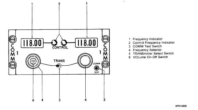
Figure 3-3. VHF Control Panel (COMM 1 - G4583A, COMM 2 - G4584A).
selection. The first method is called direct tuning
(frequency agile). The second is a channelized
operation in which desired operating frequencies are
preset, stored and referenced to a channel number.
b.
Controls/Indicators and Functions (fig. 3-4).
(1)
FREQ display. Displays frequency
selected.
(2)
Mode
display.
Displays
mode
selected.
(3)
CHANNEL display. Displays channel
selected.
(4)
Light sensor. The light sensor is a
photocell which adjust brightness of the
display.
(5)
MODE switch. The mode switch is a
momentary pushbutton switch that selects
LSB, AM or USB.
(6)
FREQ/CHAN switch. Transfers the
HF system from a direct frequency operation to a
channelized form of operation.
(7)
PGM (Program) recessed switch.
Enables channelized data to be modified. The PGM
message will be displayed whenever this switch is
depressed.
NOTE
The program mode must be used for
setting or changing any of the 99
preset frequencies. Each of the 99
channels may be preset to receive and
transmit
on
separate
frequencies
(semi-duplex),
receive
only,
or
transmit and receive on the same
frequency (simplex). The operating
mode (LSB, USB or AM) must be the
same for both receive and transmit
and can also be preset.
(8)
Frequency/channel selector. This
selector consists of two concentric knobs that control the
channel and frequency digits, plus the lateral position of
the cursor.
(a)
Frequency control. The outer
knob becomes a cursor (flashing digit) control with the
FREQ/CHAN switch in the FREQ position. The flashing
digit is then increased/decreased with the inner knob.
(b)
Channel control. The outer
knob is
3-9


