TM 55-1510-221-10
SYSTEM and/or COMPONENT
ELECTRICAL POWER
1. AC Volts/Frequency Meter
2. Battery
3. Battery Charge Monitor System and Annuncia
tor
4. DC Generator
5. DC Generator Annunciator
6. DC Load Meter
7. lnverter
8. lnverter Annunciator
ENVIRONMENTAL
1. Bleed Air Fail Annunciators
2. Altitude Warning Annunciator (cabin)
3. Cabin Rate of Climb Indicator
4. Differential Pressure/Cabin Altitude Indicator
5. Duct Overtemp Annunciator
6. Outflow Valve
7. Pressurization Controller
8. Safety Valve
9. Bleed Air Shutoff Valve
FIRE PROTECTION
1. Engine Fire Detector System and Annunciator
FLIGHT CONTROLS
1. Flap Position Indicator
2. Flap System
3. Stall Warning Horn
4. Trim Tab Position Indicator
(Rudder, Aileron, Elevator)
5. Yaw Damp System
1
1
1
2
2
2
2
1
2
1
1
1
1
1
1
1
2
2
1
1
1
3
1
1
1
1
2
2
2
2
1
2
1
1
1
1
1
1
1
2
2
1
1
1
3
1
1
1
1
2
2
2
2
1
2
1
1
1
1
1
1
1
2
2
1
1
1
3
1
1
1
1
2
2
2
2
1
2
1
1
1
1
1
1
1
2
2
1
1
1
3
1
1
1
1
2
2
2
2
1
2
1
1
1
1
1
1
1
2
2
1
1
1
3
1
One may be inoperative provided
corresponding loadmeter is moni
tored.
May be inoperative provided both
inverters are operative.
Provided bleed air is not used from
side of failed light.
May be inoperative provided air-
plane remains unpressurized.
May be inoperative provided that
the flap travel is visually inspected
prior to takeoff.
May be inoperative provided that
the trim tabs are checked in the
neutral position prior to each take off
and checked for full range of opera-
tion.
May be inoperative for flight at and
below 17,000 feet.
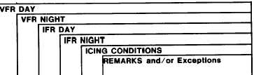
Figure 5-4. Required Equipment Listing (1 of 3)
5-13