TM 55-1510-220-10
(5) Shutdown procedure:
1.
Function selector switch (UHF control panel)-
OFF.
2.
Power switch (Voice security control panel) -
OFF.
e.
UHF Command Set - Emergency Operation:
NOTE
Transmission on emergency frequencies
(guard
channels)
is
restricted
to
emergencies
only.
An
emergency
frequency of 121.500 MHz is also
available on the VHF command radio set.
1.
Transmitter-interphone selector switch (audio
control panel) - No.3 position.
2.
Mode selector switch (UHF control panel) -
GUARD.
3.
Microphone switch - Press.
3-10. VOICE ORDER WIRE (AN/ARC-164).
A radio set identical in type and performance to the UHF
command set (fig. 3-3) is located behind the copilot's seat, to
serve as voice order wire. The TM 55-1510-220-10 set
provides the pilot and copilot with secure 2-way voice
communications. Volume is controlled through the No. 5
position on the VHF-AM Control Panel (fig. 3-1). Complete
provisions only are provided for a KY-58 voice security
device. The voice order wire set is protected by a 7 1/2
ampere VOW circuit breaker on the overhead circuit breaker
panel (fig. 2-27). The voice order wire shares an antenna
mounted on the aircraft belly with the transponder set (fig. 2-
1).
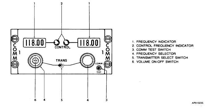
3-11. VHF-AM COMMUNICATIONS (VHF-20B).
a.
Description. VHF-AM communications provide
transmission and reception of amplitude modulated signals in
the very high frequency range of 116.000 to 151.975 MHz for
a range of approximately 50 miles, varying with altitude. A
dual head control panel (fig. 3-4) is mounted on the pedestal
extension, accessible to both the pilot and copilot. The panel
provides two sets of control indicators, frequency indicators,
frequency select knobs, a single volume control, and a single
selector switch for quick frequency changing. Transmission
audio is routed by pilot and copilot No.1 transmitter selector
switches located on the audio control panel (fig. 3-1).
Received audio is routed by pilot and copilot No.1 receiver
audio switches (fig. 3-1), to the respective headsets. The
VHF radio is protected by a 10-ampere VHF circuit breaker
on the overhead circuit breaker panel (fig. 2-27). The
associated antenna is shown in figure 2-1.
Figure 3-4. VHF-AM Control Panel (VHF-20B)
Change 2 3-9