TM 55-1510-219-10
upon aircraft altitude and ambient temperature. On
takeoff, excessive pressure bumps are prevented by
landing
gear
safety
switch
actuated
solenoids
incorporated in the flow control units. These solenoids,
through a time delay, stage the input of ambient air flow
by allowing ambient air flow introduction through the left
flow control unit first, ten seconds later, air flow through
the right flow control unit. The Bleed Air Switches,
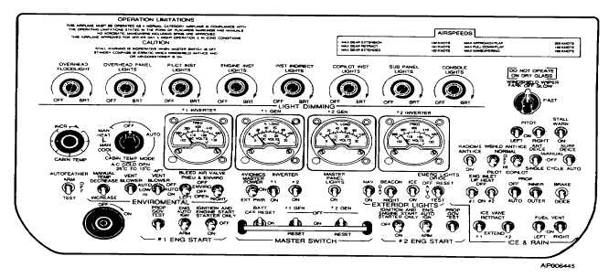
located on the overhead control panel (fig. 2-1 8) operate
an integral electric solenoid which controls the bleed air to
the firewall shutoff valves.
c.
Cabin Altitude and Rate-of-Climb Controller. A
control panel is installed on the copilot's inboard subpanel
for operation of the system. A knob (fig. 2-6), placarded
INC RATE controls the rate of change of pressurization.
A control, placarded CABIN CONTROLLER is used to set
the
desired
cabin
altitude.
For
proper
cabin
pressurization, the CABIN CONTROLLER should be set
500 feet above cruise altitude. For landing select 500
feet above field pressure altitude. The selected altitude is
displayed on a mechanically coupled dial above the
control, placarded CABIN ALT-FT. Mechanically coupled
to the cabin altitude dial, placarded ACFTX1000. This
dial indicates the maximum altitude the aircraft may be
flown at to maintain the desired cabin altitude without
exceeding the design pressure differential. A switch,
placarded
CABIN
PRESS
DUMP-PRESS-TEST,
is
provided to control pressurization. The switch is spring
loaded to the PRESS position. In the DUMP position, the
safety valve will be opened and the cabin will be
depressurized to the aircraft altitude. In the PRESS
position, cabin altitude is controlled by the CABIN
CONTROLLER control. In the TEST position, the landing
gear safety switch is bypassed to enable testing of the
pressurization
system
on
the
ground.
Operating
instructions are contained in Chapter 8.
d.
Cabin Rate-of-Climb Indicator. An indicator,
placarded CABIN CLIMB, is installed on the copilot's side
of the instrument panel (fig. 2-28). The cabin rate-of-
climb controller is calibrated in thousands-of-feet per-
minute change in cabin altitude.
e.
Cabin Altitude Indicator. An indicator, placarded
CABIN ALT, is installed in the instrument panel (fig. 2-28)
above the cabin rate-of-climb indicator. The longer
needle indicates aircraft altitude in thousands-of-feet on
the outside dial. The shorter needle indicates pressure
differential in PSI on the inner dial. Maximum differential
is 6. 1 PSI.
f Outflow Valve. A pneumatically operated outflow
valve, located on the aft pressure bulkhead, maintains the
selected cabin altitude and rate-of-climb commanded by
the cabin rate-of-climb and altitude controller on the
copilot's instrument panel.
Figure 2-78. Overhead Control Panel
2-46


