burns out. The circuit is protected by a 5-ampere circuit
breaker, placarded LANDING GEAR IND, on the
overhead circuit breaker panel (fig. 2-26).
d.
Landing Gear Warning Light Test Button. A test
button, placarded HDL LT TEST, is located on the left
subpanel. Failure of the landing gear switch to
illuminate red, when this test button is pressed, indicates
two defective bulbs or a circuit fault. The circuit is
protected by a 5-ampere circuit breaker, placarded
LANDING GEAR RELAY CONTROL, on the overhead
circuit breaker panel (fig. 2-26).
e.
Landing Gear Warning Horn. When either
power lever is retarded below approximately 80 ± 1% N
1 with the landing gear out of down and locked position
and the flaps extended beyond 40%, a warning horn
located in the overhead control panel will sound
intermittently. To prevent actuation of the warning horn
during long descents, a pressure differential "Q" switch
is connected into the copilot's static air line to prevent
the warning horn from sounding at airspeeds greater
than 140 KIAS. An altitude sensing switch is installed in
series with the "Q" switch to disable the warning horn at
altitudes above approximately 12,500 feet MSL. The
warning horn is enabled as the aircraft descends through
approximately 10,500 feet MSL. The warning horn
circuit is protected by a 5-ampere circuit breaker,
placarded
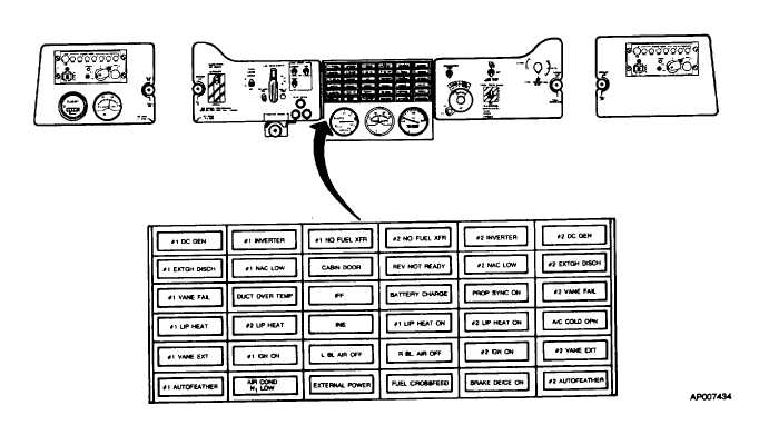
Figure 2-6. Subpanels
2-13


