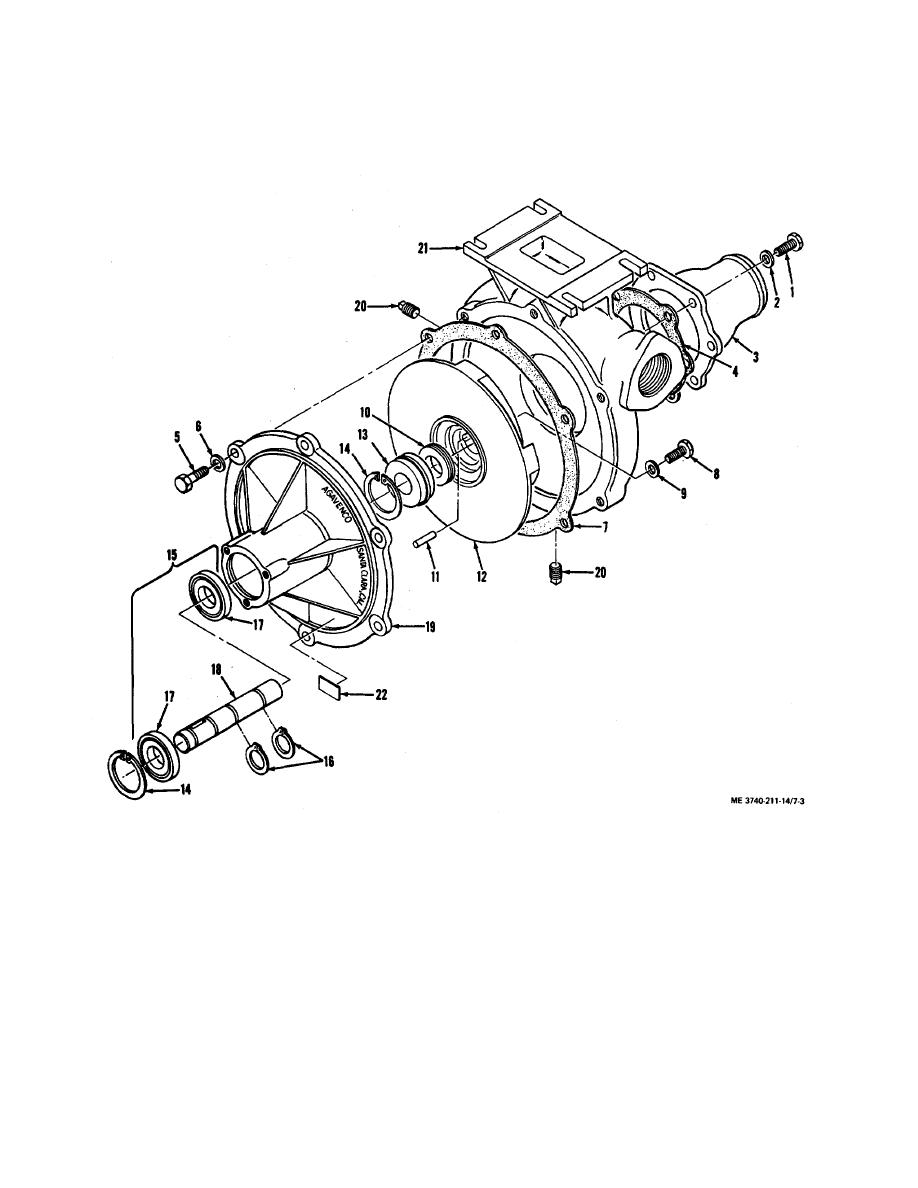
b. Remove screws (5) and washers (6) securing
Tighten this bolt against the shaft end (18) to remove
impeller. Remove bolt from impeller.
body (19) to case (21). Remove body and attached parts
d. Using two flat blade screwdrivers, pry the
(8 through 19) and gasket (7) from case.
c. Remove bolt (8) and lock washer (9) from
stationary seal (10) from the impeller. Discard seal.
Pressure should be applied evenly to both sides of seal
impeller shaft (18). Discard bolt. Insert a 3/8-16 coarse-
to prevent damage to impeller.
thread bolt into the center hole of the impeller (12).
e. Remove pin (11) from slot in impeller hub.
Threaded end of bolt must be at least 1.0 inch long.
1.
Screw
13.
Main seal
2.
Washer, AN960-416
14.
Snap ring
3.
Inlet
15.
Shaft and bearing assembly
4.
Gasket
5.
Screw
16.
Snap ring
6.
Washer, AN960-516
17.
Bearing
7.
Gasket
18.
Shaft
8.
Bolt
19.
Body
9.
Washer, Lock
20.
Plug Y%-27
10.
Stationary seal
21.
Case
11.
Pin
22.
Identification plate
12.
Impeller
Figure 7-3. Pump assembly - exploded view.
7-6


