T. O. 1-1A9
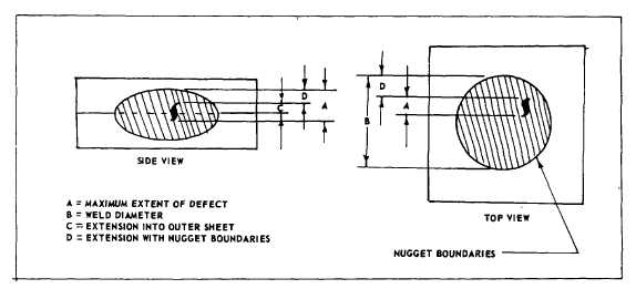
Figure 2-3. INTERNAL DEFECT - SPOT WELD
2-200. The best procedure to start the welding operation is by taking clean samples of the pile-up and testing and
adjusting machine until optimum results are obtained. The tests are started by setting pressure and dwell time for the
thinnest sheet in the pile-up and then adjusting the current and pressure to obtain a good spot/seam of the required
strength. After the production is started, the welds shall be checked frequently to assure that proper conditions are
maintained. The welds shall be inspected for proper spacing, correct size/diameter, surface appearance (welds should
be smooth and free of cracks), tip pick-up (clean tips frequently), surface flashes, explusion of weld between sheets,
blown spots, surface indentation, porosity strength, sheet separation and edge distance. See Table 2-21, 2-22, 2-23, 2-
24, and paragraph 2-201.
2-201. SURFACE INDENTATIONS LIMITATIONS. The surface (electrode) indentations for parts used in the airfoil
(aerodynamic) areas of an aerospace craft shall not exceed 0.004 inch. In other areas, parts will not be acceptable if
electrode indentations exceed the following depth limitations:
a.
For parts requiring Class A or B welds and thickness of the thinnest outside sheet in which the indentation will
occur is 0.025 inch or greater, the indentations shall not exceed 0.005 inch or 10% whichever is greater.
b.
For parts requiring Class A or B welds and thickness of the thinnest outside sheet in which the indentation will
occur, is less than 0.025 inch, the indentation shall not exceed 0.003 inch or 20%, whichever is greater.
NOTE
If the indentation requirements cited in paragraph 2-201b cannot be attained, the strength of
the weld will be the governing factor. However, the indentations shall not exceed those cited
in paragraph 2-201a.
c.
For parts requiring Class C welds, the electrode indentation shall not exceed 0.005 inch or 10%, whichever is
greater of the thickness of the sheet in which the indentation occurs.
2-202. PENETRATION AND INTERNAL DEFECTS LIMITATIONS. Weld penetration and soundness shall be
determined by examination of a metallurgical section through the center in test specimens/samples. The outline of the
fusion zone shall be generally consistent in size and regular in shape.
2-203. Internal defects of production parts such as porosity, cracks, lack of fusion, or voids will be acceptable if the
maximum extent of the defects does not exceed one of the following limits as indicated by metallographic examinations
of section (see Figure 2-3).
a.
For Class A welds 10% and for Class B welds 15% of the weld diameter and 25% for Class C welds.
b.
Twenty-five percent of the respective sheet thickness extension into an outer sheet for Classes A and B and fifty
percent for Class C.
2-204. JIGS AND FIXTURES FOR SPOT/SEAM WELDING. The jigs and fixtures for use in aligning and assisting in
assembly of welded parts that must pass through the magnetic field during the welding
2-107