TM 1-1510-225-10
3D-1
CHAPTER 3D
AVIONICS
GLOBAL POSITIONING SYSTEM KLN 90B T3 F3
3D-1. GENERAL.
a. Applicability. The KLN-90B Navigation
System is only applicable to the C-12T3 and C-12F3
aircraft. The C-12R aircraft utilize the GNS-XLS Flight
Management System to access GPS navi gation.
C-12R crewmembers may remove this chapter.
In the near future the KLN-90B will be removed
from the C-12T3 an C-12F3 aircraft and this entire
chapter will be removed from the operator's manual.
b. Description. The Global Positioning System
(GPS) is a satellite based radio navigation system that
utilizes precise range measurements from GPS
satellites to determine precise position anywhere in the
world. The KLN 90B provides en route navigation
information and non-precision (except localizer, LDA,
and SDF) instrument approach navigation.
c. Components.
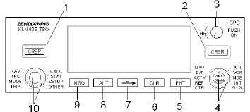
(1) KLN 90B Panel. Located above the
weather radar on the instrument panel, it contains the
GPS sensor, the navigational computer, a CRT
display, and all controls required to operate the unit. It
also houses the database cartridge that plugs directly
into the back of the unit. Refer to Figure 3D-1.
(2) External Annunciators/Switches. A panel
located just to the right of the altitude select on the
instrument panel contains switches to select OBS or
LEG during en route navigation and a switch to arm
the unit during approach. It also has annunciators to
indicate when a message is active, when waypoint
sequencing is about to occur, and when altitude
alerting is occurring. The annunciator panel also
contains a jack to load the database from a laptop
computer. Refer to Figure 3D-2.
(3) Antenna. A GPS antenna is located on
the top of the fuselage at approximately STA 220.
d. Power. Vdc to the KLN 90B is provided
through a 5 -ampere circuit breaker on the copilot’s
sidewall circuit breaker panel labeled FMS No. 2.
3D-2. DATABASE.
a. Database. The databases for the KLN 90B
have a primary and a secondary coverage area. All
databases
contain
complete
information
for
all
worldwide VOR's, NDB's, and Minimum Safe Altitudes
(MSA's). For its primary area, the database contains
public use and military airports that have any runway
at least 1000 feet in length. For its secondary area,
the database also contains airports having a hard
surface runway at least 3000 feet in length. Airport
communication frequencies and runway information
are provided only for airports in the primary area.
Intersections, air route traffic control center data, flight
service station frequencies, and special use airspace
are also provided only for the primary area. Refer to
Figure 3D-3.
1. Left CRSR
2. Right CRSR
3. Power/BRT Knob
4. Right Inner and Outer Concentric Knobs
5. ENT Button
6. CLR Button
7. Direct to Button
8. ALT Button
9. MSG Button
10. Left Inner and Outer Concentric Knobs
Figure 3D-1. KLN 90B Controls