TM 1-1510-225-10
3C-50
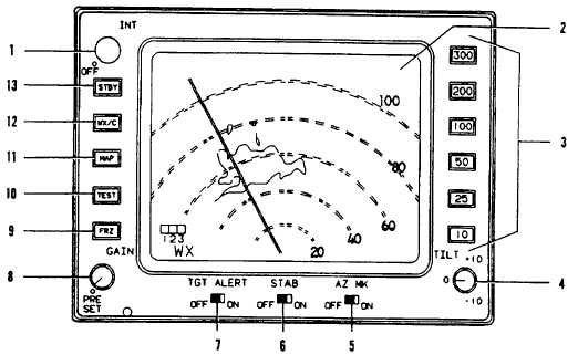
1. INT OFF
2. Display Area
3. 10 25 50 100 200 300
4. TILT
5. AZ MK
6. STAB
7. TGT ALERT
8. GAIN
9. FRZ
10. TEST
11. MAP
12. WX/C
13. STBY
Figure 3C-22. Color Weather Radar
(8) GAIN. Rotary control with one fixed-gain
detented position PRESET. Used to adjust sensitivity
of radar receiver, primarily to resolve nearby strong
target signals while ground mapping. Sensitivity
increases with clockwise rotation. Full counter-
clockwise rotation to detent sets gain at preset level.
When control is not in detented position, VAR is
displayed unless preset gain has been automatically
selected.
(9) FRZ. Momentary push button used to
turn freeze function on or off with alternate pressings.
When freeze is selected, display is not updated with
incoming target return data. To alert pilot, FRZ label is
displayed and is flashed on and off once each second.
FRZ is automatically deactivated whenever selection
of different control settings dictate a change in
displayed
data.
At
system
startup,
FRZ
is
automatically off.
(10) TEST. Momentary push button used to
select a special test pattern to allow verification of
system operation. In test position, transmitter is not
enabled, 100-mile range and preset range gain are
automatically selected, and TEST is displayed.
(11) MAP. Momentary push button used to
select ground-mapping display, MAP is displayed.
(12) WX/C. Alternate action momentary push
button used to select weather detection operation. If
WX/C or MAP is selected prior to end of warm-up
period, WAIT will be displayed until RT warms up
(approximately 60 seconds). After initial startup and
warm up, the first press of WX/C selects weather
operation and WX is displayed. The second press of
the push button selects cyclic weather display and
CYC is displayed. Displayed red targets flash on and
off once per second. Gain is automatically set to
preset level.
(13) STBY. Momentary push button used to
select standby after radar has been used in an
operating mode; e.g., WX or TEST. Standby is useful
for keeping radar in ready state while taxiing, loading,
etc. In standby, antenna does not scan, transmitter is
not enabled, and display memory is erased. STBY is
displayed in Mode Field and 100 is displayed as the
selected range numeric.