TM 1-1510-225-10
3C-36
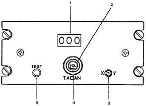
1. TACAN Channel Display
2. VOL On/Off Knob
3. X/Y Switch
4. Channel Selector/Volume Control
5. TEST Push Button
Figure 3C-16. TACAN Control Panel
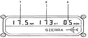
1. Distance To Station N.M. (Slant Range)
2. Groundspeed (KTS)
3. Time To Station (Minutes)
Figure 3C-17. TACAN Indicator
NOTE
THE TACAN portion of a VORTAC station
will be read on the HSI only when the
proper channel is selected on the TACAN
control panel and TACAN is selected with
the HSI selector switch. With VOR
selected, the VIR-32 receivers are tuned to
the VOR portion and the DME-42 receives
the DME portion.
The TACAN system may be operated on the
flight director system or connected to and used with
the autopilot system. When employed as the primary
means of navigation, aircraft flight may be controlled
manually or by the autopilot magnetic bearing to
TACAN stations may be shown on the RMI's when the
VOR ADF / TACAN ADF push buttons, to the lower
left of the pilots' RMI and to the far right of the copilot's
instrument panel, are pressed to the TACAN ADF
position. Also, the VOR ADF push button for the #1
(yellow) needle on the RMI’s must be pressed to the
VOR position. Course deviation only may be shown
on the HSI’s when the TACAN selector for the HSI is
pressed. TACAN slant range is displayed on each HSI
range in the digital distance display. TACAN distance,
groundspeed, and time-to-station are all displayed on
the
TACAN
indicator
located
on
the
copilot’s
instrument panel.
NOTE
Under conditions of bright direct sunlight,
the VOR ADF / TACAN ADF push button
indicate the selected channel.
The TACAN control panel enables selection of
the TACAN frequency (channel) to be used and
provides self-test of TACAN circuits. X or Y channel is
selected by the X / Y switch. Y channels differ from X
channels in frequency assignment and pulse spacing.
Y channels were developed to relieve frequency
congestion. Use of the Y channels has been
implemented
along
with
0.05 MHz
spacing
for
VOR/VORTAC stations and Y channels are paired
with these new frequencies (for example, VOR
frequency 113.1 is TACAN channel 78X; VOR 113.15
is TACAN channel 78Y). DoD FLIP charts will include
the Y designation in the data block for Radio Aids to
Navigation. The small (outer) control provides system
power ON / OFF and station identity tone volume
control. TACAN circuits are protected by a TACAN
circuit breaker on avionics portion of the copilot's right
sidewall panel.
b. Controls, Indicators, and Functions.
(1) TACAN Control Panel. Refer to Figure
3C-16.
(a) TACAN Channel Display – Indicates
selected channel.
(b) VOL On/Off Knob – Provides system
power and volume control.
(c) X / Y Switch – Selects either X or Y
mode.
(d) Channel Selectors – Selects desired
channel.
(e) TEST Push Button – When pressed,
activates functional self-test.
(2) TACAN Indicator. Refer to Figure 3C-17.