TM 1-1510-224-10
the navigation source displayed in white letters.
Possible annunciations are ADF, VOR1, INS, and TCN.
(21)
Weather radar tilt angle display. The
weather radar tilt angle display (green) shows the angle
that the weather radar antenna is tilted upward or
downward from level in degrees plus or minus.
(22)
Weather radar mode annunciator. The
weather radar mode annunciator indicates the operating
mode of the radar system. Possible annunciations in the
full compass format of the EHSI are TX (magenta) and
WX (amber). TX indicates that the radar is transmitting
but not being displayed. WX indicates a weather radar
system failure. Possible annunciations in the partial
compass format are standby (STBY), test (TEST),
weather
detection
(WX),
rain
echo
attenuation
compensation
technique
(RCT),
ground
mapping
(GMAP), and fall (FAIL).
All
partial
compass
annunciations are green except FAIL, which is amber.
(23)
Weather radar target alert and variable
gain annunciator. The green TGT annunciator indicates
that the target alert function of the weather radar has
been selected. The amber VAR annunciator indicates
that variable gain has been selected.
(24)
Lightning
sensor
system
mode
annunciator
The lightning strike sensor system mode annunciator
indicates the operating mode of the lightning sensor
system. Possible annunciations are LX, LX/F, LX/S,
LX/T, LX/H, LX/1, LX/C, LX/L, and LXMN. All
annunciations are green except LX/F and LXMN which
are amber. These mode annunciators are described in
the lightning sensor system paragraph in this chapter.
(25)
Compass
system
synchronization
annunciator. The compass synchronization system
annunciator indicates the state of the compass system in
the slaved mode. The bar represents commands to the
compass gyro to slew to the indicated direction (+ for
increased heading and 0 for decreased heading).
Compass synchronization annunciation will be removed
during the compass free gyro mode. If the cross-side
compass display has been selected, the synchronization
annunciator will be removed.
c.
EHSI Partial Compass Format (fig. 3-15). The
partial compass mode displays a 90-degree arc of the
compass card. The following additional features are
available during partial compass operation:
(1)
Range rings. Range rings are displayed
to aid in the use of radar returns and position of navaids.
The outer range ring is the compass card boundary and
represents the selected range on the radar. Range
annunciation
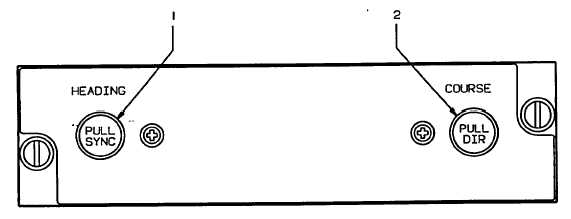
1. Heading Knob
2. Course Knob
A93FE00D0I03 C
Figure 3-14. Flight Director Remote Heading/Course Control Panel "
3-34


