TM 1-1510-223-10
2-44
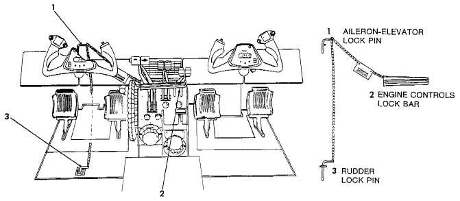
Figure 2-23. Control Locks
control wheel. Depressing the switch to the first of two
levels disconnects the autopilot and yaw damp system
and the second level disconnects the electric trim sys-
tem. The system can be reset by moving the ELEV TRIM
switch toggle on the pedestal (fig. 2-12) to OFF/RESET
position, then back to ELEV TRIM again.
c. Aileron Trim Tab Control. The aileron trim tab con-
trol, placarded AILERON TRIM - LEFT, RIGHT, located
on the control pedestal, adjusts the aileron trim tab (fig.
2-12). The amount of aileron tab deflection from a neutral
setting, as indicated by a position indicator, is relative
only and is not in degrees.
d. Rudder Trim Tab Control. The rudder trim tab con-
trol, placarded RUDDER TAB - LEFT, RIGHT, located on
the control pedestal, controls adjustment of the rudder
trim tab (fig. 2-12). The amount of rudder tab deflection,
in units from a neutral setting, is indicated by a position
indicator.
2-40. WING FLAPS.
The slot-type wing flaps are electrically operated and
consist of two sections for each wing. These sections ex-
tend from the inboard end of each aileron to the junction
of the wing and fuselage. During extension or retraction,
the flaps are operated as a single unit, each section being
actuated by a separate jackscrew actuator. The actua-
tors are driven through flexible shafts by a single revers-
ible electric motor. Wing flap position is indicated in
percent of travel by a flap position indicator on the center
subpanel. Full flap extension and retraction time is
approximately 11 seconds. The flap control switch is lo-
cated in the control pedestal. No emergency wing flap ac-
tuation system is provided. With flaps extended beyond
the APPROACH position, the landing gear warning horn
will sound, unless the landing gear is down and locked.
The circuit is protected by a 20-ampere circuit breaker,
placarded FLAP MOTOR, located on the overhead cir-
cuit breaker panel (fig. 2-7).
a. Wing Flap Control Switch. Flap operation is con-
trolled by a three-person switch with a flap-shaped handle
on the control pedestal (fig. 2-12). The handle of this
switchisplacardedFLAP.Switchpositionsareplacarded:
FLAP - UP, APPROACH and DOWN. The amount of ex-
tension of the flaps is established by the position of the
flap switch as follows: UP - 0%, APPROACH - 40%, and
DOWN - 100%. Limit switches, mounted on the right in-
board flap, establish the flap travel. The flap control
switch, limit switch, and relay circuits are protected by a
5-ampere circuit breaker, placarded FLAP CONTR, lo-
cated on the overhead circuit breaker panel (fig. 2-7).
Intermediate flap positions between UP and APPROACH
cannot be selected. To return the flaps to full UP, place the