TM 1-1510-218-10
3C-12
3C-10. HF
COMMUNICATIONS
TRANSCEIVER
(KHF 950).
a. Description.
The
HF
communications
transceiver provides long-range voice communications
within the frequency range of 2.0000 to 29.9999 MHz
(280,000 possible frequencies). The unit can employ
either amplitude modulation (AM), upper sideband
(USB)
modulation,
or
lower
sideband
(LSB)
modulation. The KHF-950 HF system consists of a
KCU-951 control display unit located on the pedestal
extension (Figure 2-9), a KTR-953 receiver/exciter,
and KAC-952 power amplifier/antenna coupler (the
latter two items are located aft of the rear pressure
bulkhead). The system is powered through a
25-ampere circuit breaker placarded HF PWR, and a
5-ampere circuit breaker placarded HF REC. Both
circuit breakers are located on the overhead circuit
breaker panel (Figure 2-16).
b. HF
Transceiver
Control/Display
Unit
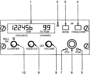
Controls and Functions. Refer to Figure 3C-4.
(1) Digital Display. A digital display located
on the upper left portion of the control display unit
provides frequency, mode, and operational status
information. The upper (larger) display shows 6-digit
frequency information, and two-digit channel numbers.
The lower (smaller) display shows signal emission
mode (LSB, AM, and USB) transmitter operation (TX),
and program mode (PGM). Display brightness is
controlled by a dimming control, placarded HF, located
left of the altitude alert indicator on the instrument
panel.
(2) Photocell. A photocell, located to the
right of the display, senses ambient light conditions
and adjusts display brightness accordingly.
(3) Emission Mode Switch. A push-button
switch placarded MODE, located on the HF control
unit,
selects
transmission
and
reception
mode.
Momentary pressing of the MODE switch cycles the
system from Upper Sideband (USB) mode, to Lower
Sideband (LSB), to Amplitude Modulation (AM)
modes. Mode selection is indicated on the display by
the illumination of the respective USB, LSB, or AM
annunciators.
(4) Frequency/Channel Switch. A two-
position push-button switch, placarded FREQ/CHAN,
located on the upper right portion of the HF control unit
controls the method of frequency selection. When the
switch is in the out position, the system is in the direct
frequency tuning (simplex) mode. When the switch is
in the pressed position, the system is in the preset
channel mode.
1. Digital Display
2. Photocell
3. Emission Mode Switch
4. Frequency/Channel Switch
5. Program Switch
6. Tuning Knobs
7. Store Switch
8. OFF/Volume Control
9. SQUELCH Control
10. CLARIFIER Control
Figure 3C-4. HF Transceiver Control-Display Unit
(KCU-951)
(5) Program Switch. A momentary push
button switch, placarded PGM, located on the lower
right side of the HF control unit, causes the system to
enter the program mode when pressed. When the
system is in the program mode, frequencies and the
transceiver emission mode may be assigned to a
preset channel number and stored in the memory for
future use.
(6) Tuning Knobs. Two concentric tuning
knobs on the HF control unit are provided to set
frequencies and preset channel numbers. The outer
knob becomes a cursor control (flashing light) with the
frequency/channel switch in the FREQ (out) position.
The cursor is moved over the digit which is to be
changed by rotating the outer concentric tuning knob,
causing the digit to flash. The flashing digit can then
be changed by rotation of the inner concentric knob.
When all digits have been changed, the cursor should
be stowed by moving it to the right or left of the
display, then turning the tuning knob one more click to
position the cursor off the display. To recall the
flashing cursor, twist the larger concentric tuning knob
in either direction until the cursor reappears.
(7) Store Switch. A momentary push-button
switch, placarded STO, is located on the HF control


