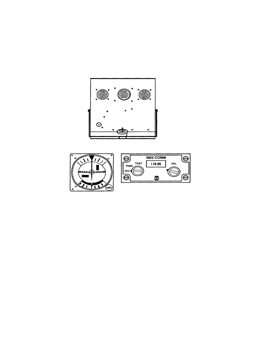
TB 43-0123
AN/ARN-82
JGO
AN/ARN-82A
JGV
AN/ARN-82B
JG5
AN/ARN-82 A/B Radio Set
been increased to twice as many channels by changing
1. Brief Description: Radio Set AN/ARN-82( ) receives
the channel spacing using the C-6873B/ARN-82 control.
very high frequency omnirange (VOR) and localizer
signals in the frequency range of 108.00 to 117.95
The AN/ARN-82 consists of:
megahertz (MHz) from a ground transmitter. The signals
C-6873/ARN-82 ..........................
Control
are demodulated and used to drive course selector
ID-1347/ARN-82 .........................
Course Indicator
indicators and radio magnetic indicators. Audio signals
or
may also be received in the communications band from
IF-1347C/ARN-82
118.00 to 126.95 MHz. Glide slope information is fed to
MT-3600/ARN-82. ......................
Mount
the course indicator from a separate glide slope receiver
R-1388/ARN-82 ..........................
Receiver
which is controlled by the AN/ARN-82( ).
The
The AN/ARN-82A consists of:
combination of the localizer capability and glide slope
C-6873/ARN-82 ..........................
Control
capability makes up an instrument landing system (ILS).
or
The frequency range of the AN/ARN-82( ) is 108.00 to
C-6873A/ARN-82
126.95 MHz with 50 kHz channel spacing. The input
ID-1347A/ARN-82.......................
Course Indicator
power requirements are 1.0 amp at 28 volts DC and 6
or
volt amps at 28 volts AC 400 Hz. The AN/ARN-82A
ID-1347B/ARN-82
differs from the ANIARN-82 in that it is not affected by
or
rotor modulation. The ANIARN-82B differs in that the
ID-1347C/ARN-82
ILS and DME capability (from associated receivers) has
ll-B-7


