
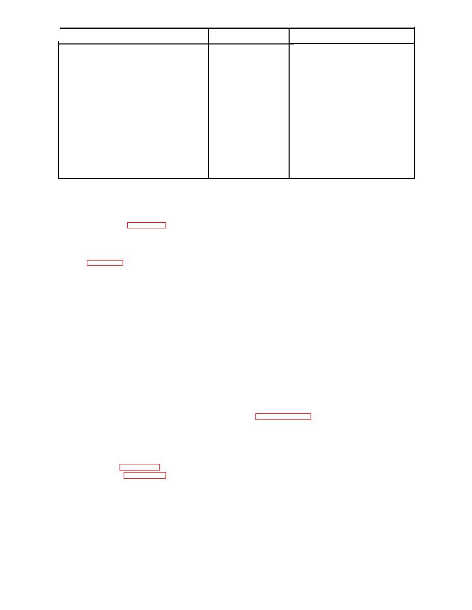
Application
Nomenclature
Part or Type Number
Monitors line voltage
Weston Model 433, 0-150V ac (or
Line voltage meter
equivalent)
Measures AC
Hewlett-Packard Model 400H (or
Vacuum tube voltmeter
equivalent)
General Radio Model V-5 (Variac). 5 amperes
Varies line voltage
Voltage changer
(or equivalent)
Kron-hite Model 466 (or equivalent type
Audio oscillator
Supplies test signal
which has a range from 5 cps to 5000 cps)
Measures voltages and resistances
Triplett Model 630A (or equivalent meter of
20,000 ohms/volt)
RCA Model WV-77A (or equivalent)
For high impedance measurements
Voltohmist
Tektronix Model 545 (or equivalent)
Visual observation of waveforms
Figure 1-24. Test Equipment Required for Test and Maintenance of the Vibration Meter Type 1-117-0105
1-53. TEST EQUIPMENT REQUIRED. Required test
1-56. REPAIR AND REPLACEMENT. (GENERAL.)
equipment for testing and maintenance of the vibra-
If visual inspection or troubleshooting indicate the
tion meter is listed in figure 1-24.
replacement or repair of resistors, capacitors, vari-
able resistors, transformers or similar components,
1-54. TROUBLESHOOTING. A study of the trouble-
such components should first be separated with care
shooting information contained within the subsequent
from instrument chassis. After removal of defec-
paragraphs will necessitate frequent reference to the
t i v e component, replace it with new or repaired
schematic, figure 1-25. Under normal operating con-
p a r t , making the appropriate solder connections.
ditions, the vibration meter should require very little
attention beyond replacement of fuses, vacuum tubes
and such defective parts as can be located by visual
inspection.
located on the rear panel of the instrument can be
removed by unscrewing the holder knob. To check
1 - 5 5 . If visual inspection, tube replacement and
fuse, remove fuse cartridge from holder. If cart-
simple component replacement does not eliminate the
ridge is burned out, replace with spare. A spare
instrument trouble, or the difficulty is faulty opera-
fuse of the correct value is located on the terminal
tion rather than failure to operate, the fault probably
board directly behind the front panel. To reach the
l i e s in the vibration transducer, interconnecting
spare fuse, first separate the instrument chassis
cables, or in the wiring circuitry associated with
assembly from the case by removing four screws
these components. Component values are often critical
located on the bottom and side of the case.
a n d considerable caution should be exercised in
soldering any connections, wiring, or parts that need
repair or work. Variable resistor R47 (see figures
1-58. REPLACEMENT OF PILOT LAMP. To re-
1-25 and 2-14) is in the circuit for the purpose of
place the 0.25 ampere, 6-8 volt pilot lamp located
adjusting the filament voltages of tubes V1 and V2.
at bottom left on the front panel, separate the in-
This control is set at the factory and should need no
strument chassis assembly from the case as outlined
in paragraph 1-57. After the chassis assembly has
attention. If, however, insufficient gain is indicated,
the filament voltage should be checked and, if neces-
been withdrawn from the case, remove the burned-
sary, an adjustment made. This check should indicate
out bulb from the pilot lamp holder and replace
approximately 6.3 volts dc for normal operation of the
with the spare.
meter. All filament voltages should be measured with
a Triplett Model 630A, or equivalent, 20,000 ohm/
1-59. DETERMINING THE ACCURACY OF INTER-
NAL CALIBRATION OF VIBRATION METER.
volt multimeter. See figures 1-26 and 1-27 for typical
instrument voltages. Figure 1-28 lists the troubles,
a. With the OPERATION selector switch in the C
probable causes and remedies which apply in case
position, depress the CALIBRATE SIGNAL control
of instrument failure or malfunction.

