TM 1-5855-265-20
3-81
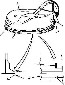
3-16. PNVS SHROUD ASSEMBLY INSTALLATION (cont)
12. Install PNVS shroud assembly (9) on turret
base.
a. Continue lowering PNVS shroud assembly
(9) along the same sloped path started in
step 9. Stop when rim (15) of PNVS shroud
assembly at point (13) is about 1/2 inch
above rim (6) of turret base.
b. Gently lower point (12) until PNVS shroud
assembly (9) is level.
c. Line up alinement stripe (20) on PNVS
shroud assembly (9) with alinement groove
(7) or pen mark on rim (6), as applicable.
d. Gently push PNVS shroud assembly (9)
down until all of rim (15) mates evenly with
all of rim (6) and alinement marks are lined
up.
13. Have PNVS shroud assembly installation
inspected.
14. Perform followup.
END OF TASK
LOWER
PUSH
15
9
12
6
15
6
CROSS SECTION
VIEW
ALINEMENT
MARKS
7
312-010C
20
13